
Background
I have a 50+ year-old garage door at my house. It generally works well enough, however, presumably due to its age, I've run into a few issues. The original issue I ran into was the door not fully closing or opening. I did a brief examination of the door and noticed the belt was whithering away, and tied this symptom to this. I replaced the belt and also noticed there is a large washer that applies tension to the belt. As part of this fix I also added some rubber to the back of the washer to apply more friction to the tensioner. These two remedies seemed to work well enough for a few months.
Eventually, I walked past the garage and heard a low humming sound. On entering the garage I immediately recognized this as the sound of the motor running. Upon inspection, the motor was attempting to close the already closed door. I'm not sure how long it was in this state, but the motor was extremely hot to the touch and it stopped itself before I could unplug it.
I unplugged the unit and let the motor cool off for a few hours before returning. I attempted to restart it and the switch seemed to work, but the motor itself would not run.
After some poking around at the unit and tracing wires, I found a large capacitor that feeds into the motor. Some internet searches and multimeter testing confirmed that this was the culprit. I managed to find an exact GE factory replacment (which is amazing considering the age of the unit) and after a few days the motor was running again. Unfortunately, the motor did not ever stop once running. I could switch directions, but it would not stop. Clearly this is the main issue that produced the preceding conditions.
I unplugged the unit and searched around for any diagrams or manuals for the unit with no luck. I then traced the wires throughout the unit to try to get an idea of how it works. Eventually I decided to take it apart, plug it in, and watch it work which provided the best results.
How it Works
The unit has a transformer, start motor capacitor, the motor itself, a relay, three stop switches, and a light socket.
The transformer powers the relay, which switches the direction the motor turns. The motor turns a belt that turns a large screw attached to a gear, which turns a chain contained within the unit itself. On a side note, the door is counterweighted with actual bricks contained in the top of the unit.
The problem is with the screw that is turned by the motor belt. This screw has a plastic nut with a slot that holds a pin. The belt movement moves the plastic nut in either direction, which is supposed to move the pin in the nut along a slot in the face plate until it ultimately physically pushes down the switches on either side. These switches are what ultimately stop the movement of the motor and kill power to the door light socket. Its a pretty cool design, honestly.
The problem is that the plastic nut was not securing the pin effectively. It would come loose and eventually fall out, which burned out the capacitor on the motor. I tried to just fix the plasic gear, then I tried replacing it with no luck on either. Next I looked for a different method to kill the motor. I found these NC/NO door sensors and figured this would make sense to use. I could align the sensors so that the door would stop once it was actually fully closed or fully open. The problem with that is, these sensors are not made for this voltage and burn out after a handful of uses. Back to square one.
I could not find a magnetic switch that worked for this application. I started looking for other switches, but eventually came to the conclusion that I would just be making a cheap knock-off of the mechanism that failed. Then it hit me, why not use the magnetic sensors correctly?
Raspberry Pi
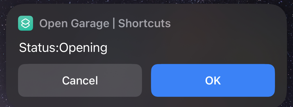
Raspberry Pi (RPi) is a low cost microcontroller primarily used for IoT applications. I could replace the door controller completely, all I would need is a way to programmatically turn the motor on. The magnetic sensors would tell the microcontroller the location of the door, and the RPi would handle the open/close logic. As an added bonus, the RPi can host an API to accept commands from a phone. The momentary switches that control garage doors work essentially the same way as the NO magnetic switches also.
The RPi could watch the door switches, check the sensors for door location, and trigger remotely from another device. It could also check an optical sensor for obstructions and stop the door, a feature this 50+ year-old door does not have.
Sounds like a win. No moving pins required.
Assembly
- Raspberry Pi 4 (the 4 is not required, a 3 should work. You could technically get 3 zeros/picos for this.)
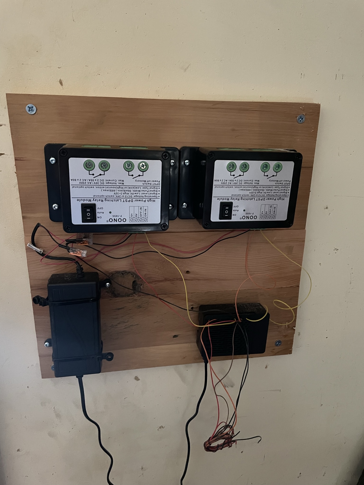
- 2 High Voltage Relays
- Ribbon Pin Wires
- Soldering Iron (optional)
- WAGO Wire Nuts (optional)
- 2 NC NO Magnetic Switches (optional)
- Optical Sensor (optional)
- Rain Sensor (Optional)
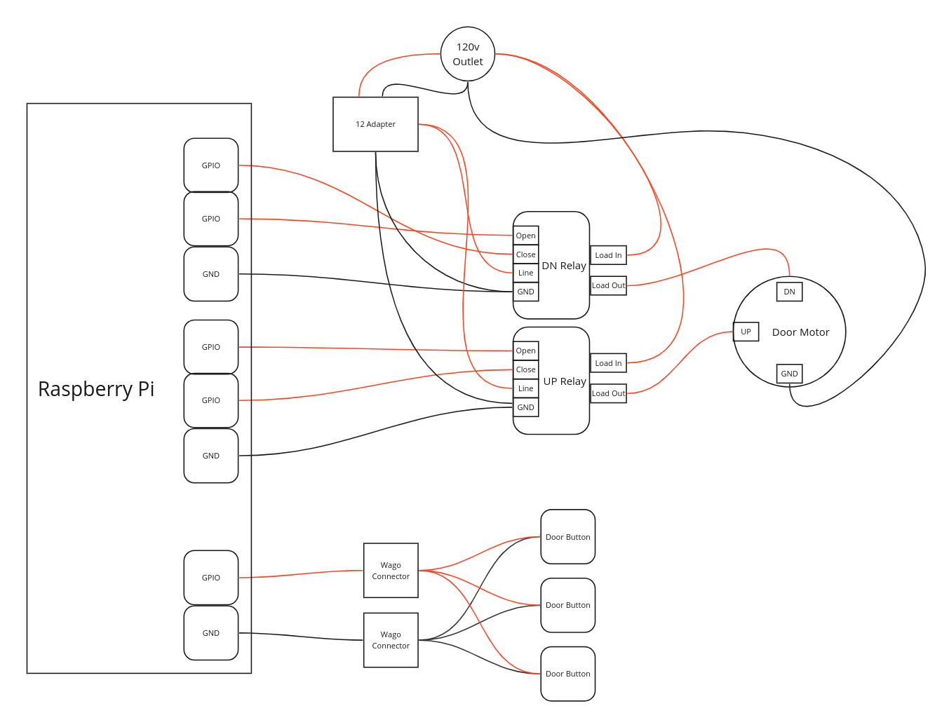
Start by mounting the RPi to an appropriately-sized board with the GPIO pins facing inwards. I used a scrap piece of wood cut down to approximately 2'x 2'. Align the relays with the controller blocks facing the RPi and mount them to the board.
Assemble the ribbon wire connectors for the DIY ribbons. I don't recommend this, it was a total pain. Just buy the premade wires and call it a day. Pay close attention to the pins you choose for this and note them down. You will need to know which pins go where.
Connect the relays to the RPi. The relays require a GND pin and two GPIO pins. One GPIO pin closes the relay and the other opens the relay. One to turn on the motor and one to turn it off. You will need to do this for each relay, for a total of four GPIO pins and two GND pins.
Make sure you know exactly which GPIO pin goes to which relay and which function on that relay.
For the switches/sensors (garage door, magnetic switches, optical sensor), you will need one GND and one GPIO each. Wire the pins before mounting the assembled unit to the final location. I would wire pins for every accessory you may want prior to mounting it, even if it may be a while before you actually add the accessory.
Logic
I thought the logic would be the easy part, and it isn't overly complicated. However, there was a lot of trial and error. Set yourself up to handle an iterative production and you'll be better off.
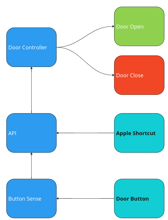
There are three main processes to account for (plus one for each sensor): Door controller, API, and a button watcher.
Each process should be standalone and self-contained with a mock process that will allow you to test logic without a real execution. Additionally, the entire operation should be configurable easily.
Let's start with the button watcher. This process runs in an endless loop with the only task of watching the door switches and sending a message to the API process if triggered. The mock process for this service will merely print out if a button was activated to the console.
Next the API. This is a simple API with only two endpoints: GET:'/gate/status' and POST:'/gate/activate'. All of the communication to the door controller comes through the API. The button watcher calls the API which, in turn, sends a message to the door controller through Redis. The API also checks for duration between requests. This is to prevent duplicate requests and to protect the equipment. The loop for the button watcher iterates 8 times per second (configurable via the config file), so a single press by a human may actually be logged 8 times within a second. Obviously, we don't want to trigger the relays in such a way. There are a plethora of potential improvements that can be made to this process, and the beauty of this set up is that this can be completely refactored remotely without having to actually touch the equipment. I will polish this code up eventually, but I'm happy with the way it works at the moment.
Finally, we have the door controller. The door controller watches a message queue for instructions on what to do and then triggers the relays to perform the activation process for the appropriately relay. The activation process is essentially: send OPEN signal both relays to ensure there is no conflicting action, send a CLOSE signal to the relay to be activated, wait for the specified duration, then send an OPEN pulse to both relays again.
That's pretty much it, and now I have a garage door that works like a charm that I can activate from anywhere the WiFi covers as well as the existing buttons.
The code for this project can be found here

Potential improvements:
- Make the logic for each service to operate optimally contained within its own process. The API handles the duplicate requests generally. Technically each process should have its own de-duplication logic. The button sense process should know what a false positive looks like and ignore it for example. The Door Controller should be able to read messages from different components and handle them appropriately. For example, say the Door Controller gets a message from the API and Button Watcher, the door controller should be able to manage that effectively.
- Use the message queue to send signals directly from the Button Watcher to the Door Controller. The above is a prerequisite for this.
- Optimize the relay activation process to provide quicker feedback. Right now, there is slight delay in order to make sure the operations are safe. The pause duration is probably overkill and the pulse signal can likely be shortened.
- Give the Pi a static IP (I know lol)
- Add the obstruction sensors and logic to hand obstructions. Potentially this could be a computer vision solution as well, since the door opens outward the potential obstruction space more complex than a standard door.
- Add a rain/water sensor. This door opens outwards and when it rains heavily with the door water pools on top of it and drains into the garage. If there is rain, the door should keep a slope that forces water to drain out.